What is a Diaphragm?
In buildings, a diaphragm is a horizontal (or near sloped) rigid floorplate element (such as a floor slab or roof deck) which transfers lateral (horizontal) loads to the main building lateral stability system. This is a key feature of diaphragms. Diaphragms can be rigid, semi-rigid, or flexible.
Examples of Valid Diaphragms
Key examples of floor systems which tend to provide rigid diaphragms include:
- Concrete on metal deck (composite deck) flooring
- Solid RC slabs
- Precast planks with structural screed topping
- CLT slabs
- Timber joist floors with plywood sheathing
- CLT floors
Examples of Poor/Flexible Diaphragms
- Roof metal decking
- Roof sheeting / cladding
These are usually too thin and flexible to provide any meaningful load transfer to the vertical lateral stability system. In these cases, the floor framing is usually supplemented by horizontal bracing (in the same plane as the floor itself) to find a direct path to braced bays or other lateral stability systems.
Diaphragm Behaviour for Rigid / Semi-Rigid Diaphragms
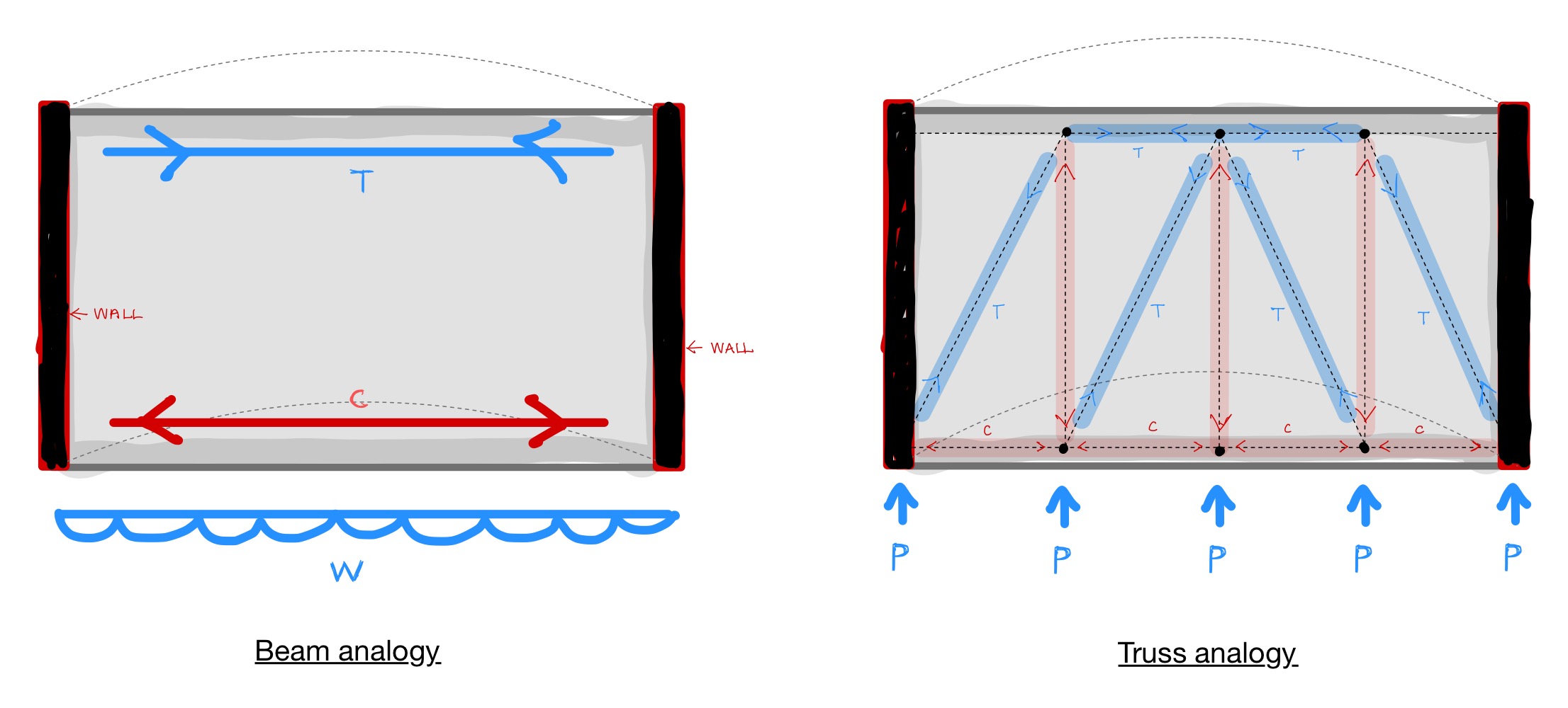
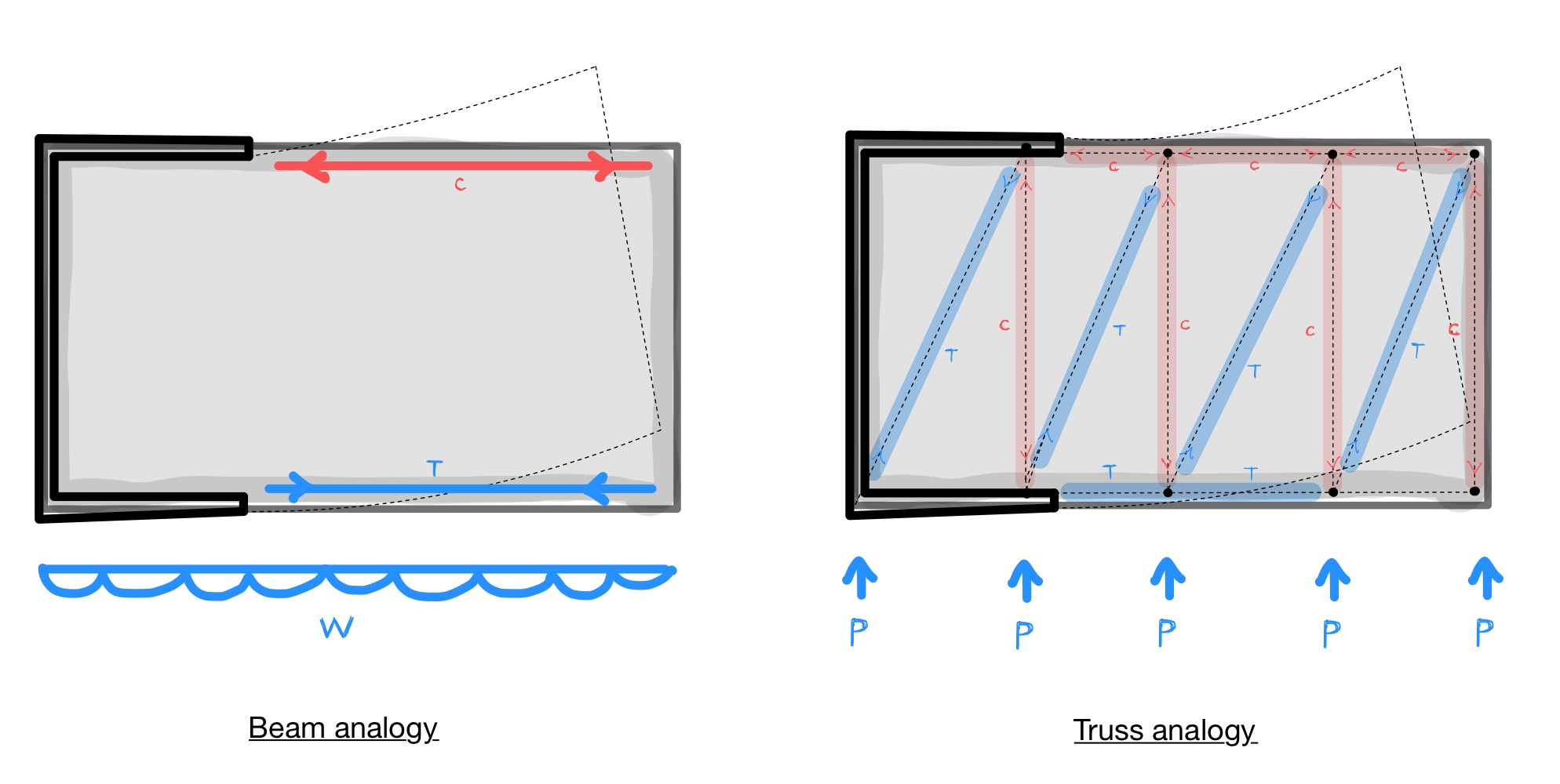
A stiff diaphragm should be able to transfer forces to the main vertical lateral stability system, such as shear walls or cross-braced bays. In some cases, you can view the diaphragm as acting like a simple-supported beam, or cantilever, depending on the arrangement of the lateral stability system (this is called the beam analogy). Another way to look at them is to draw out a strut-and-tie diagram using a truss analogy, as you can see below. A few cases to illustrate this in action are shown below:
01. Floor plate with shear walls on each side
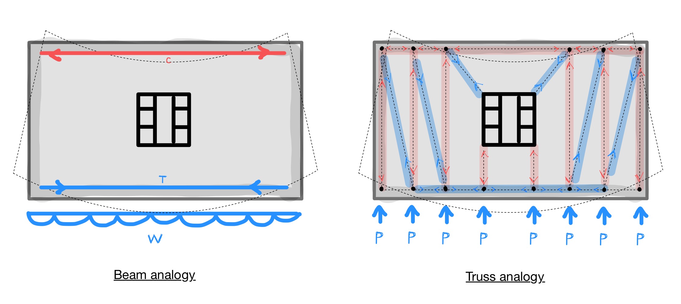
02. Floor plate with a central core
03. Floor plate with offset C-shaped shear walls
Consideration of Diaphragm Discontinuities
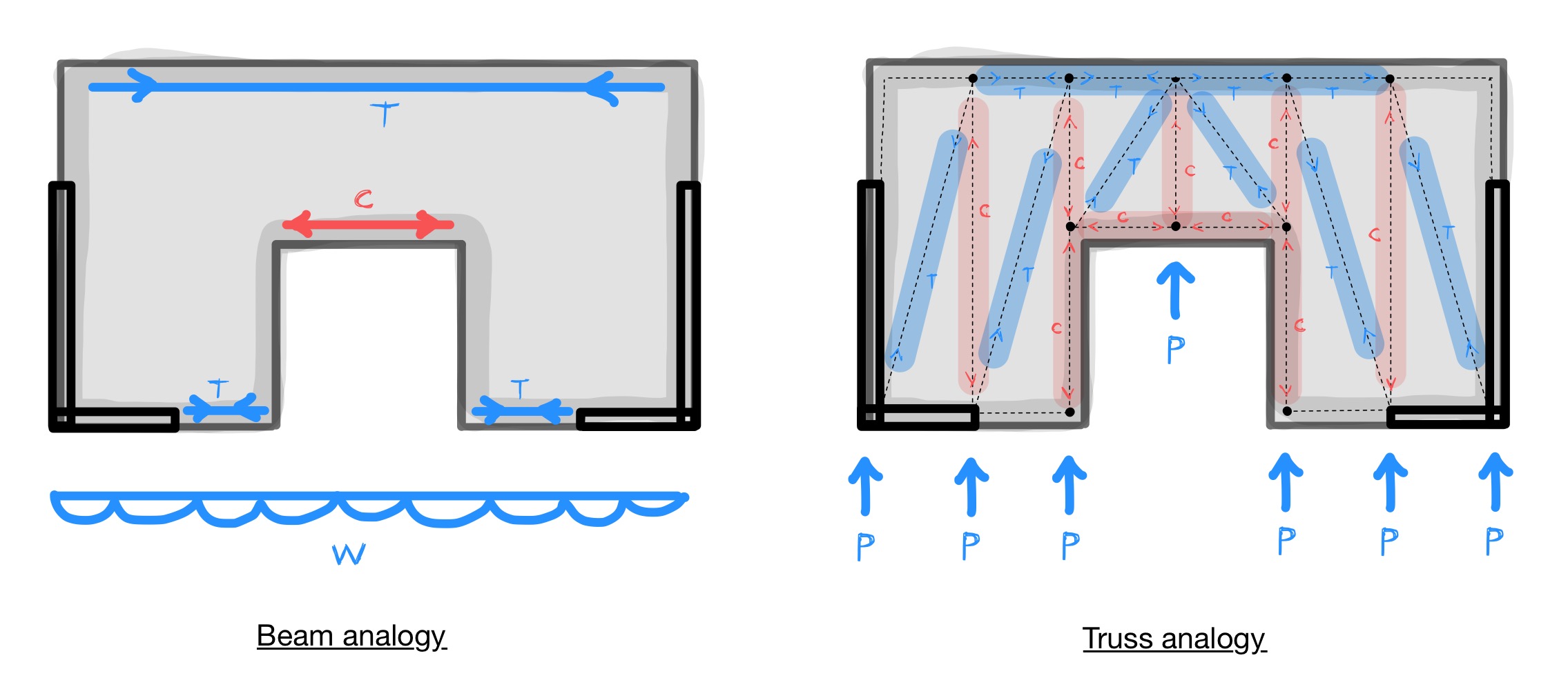
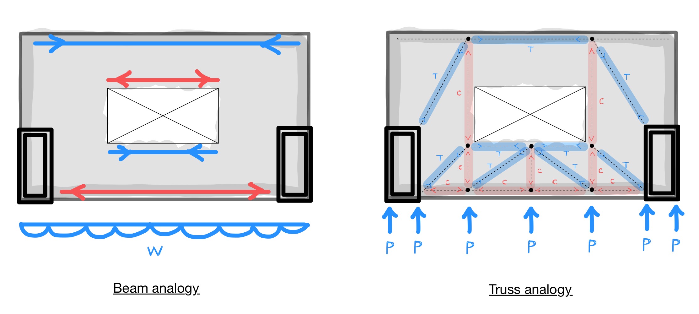
This is a critical consideration since diaphragm discontinuities will disrupt the load paths of the horizontal loads back to the lateral stability systems. In these cases, you need to check that there is a clear load path, typically using a strut-and-tie analogy. See some examples below.
04. Shear walls on both sides and large setback in middle of floor plate
05. Atrium openings in centre of floor plate
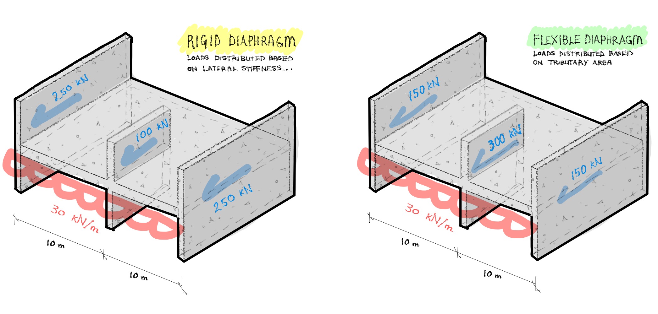
Rigid vs Flexible Diaphragms
In a rigid diaphragm, the horizontal loads are transferred to the main vertical lateral stability systems (e.g. shear walls) based on their relative stiffness. In a flexible diaphragm however, horizontal loads are transferred to the main lateral stability systems based on their respective tributary areas.